4 Pipe Hvac System Diagram
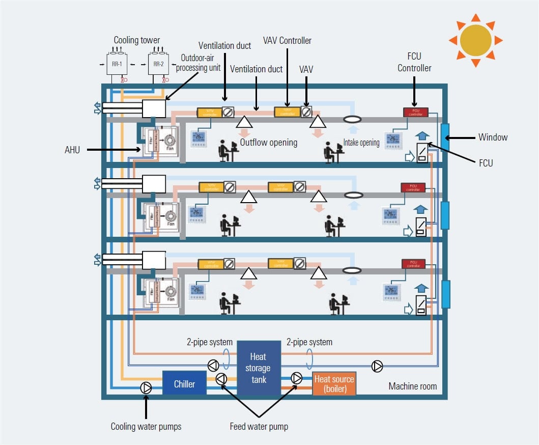
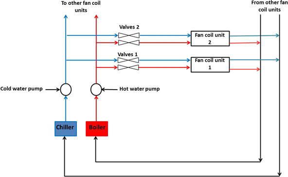
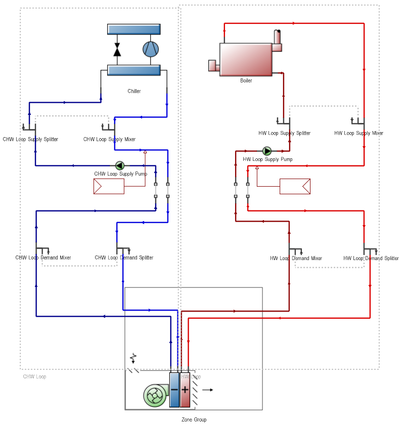
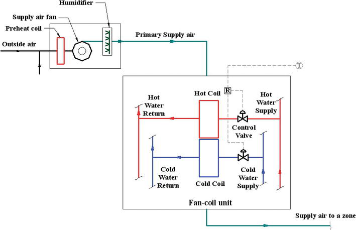
4 pipe hvac system diagram. A 4 Pipe Fan coil system is a dual closed loop supply and return water distribution system that serves each suite. There are different parts for a HVAC system based on its application but one can consider what occurs in a evaporative cooling system as a widely used case throughout the world and get a sense of what is generally happening in the system. Overall the majority of the buildings on campus.
The required system pipe diameter for example may change if the indoor unit capacity indoor unit type or pipe length fluctuates. Two-pipe originated 50 or 60 years ago as a cost-effective way to add air conditioning. Pipes used in the system 1-pipe 2-pipe 3-pipe and 4-pipe.
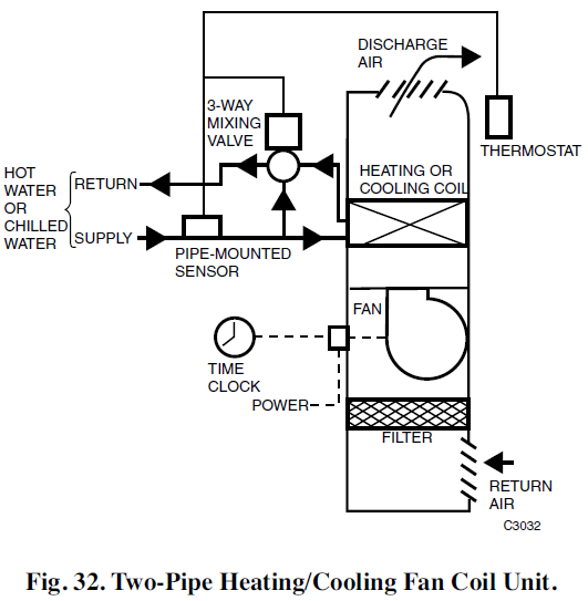
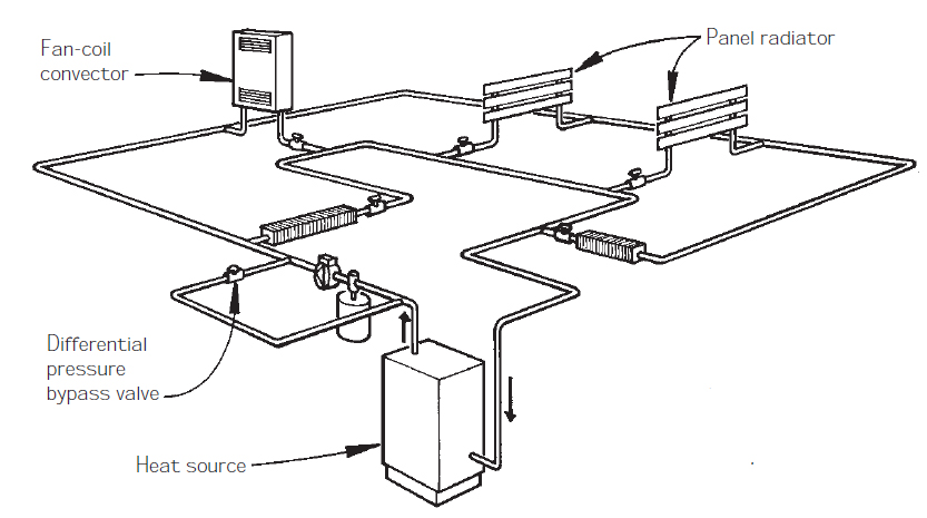
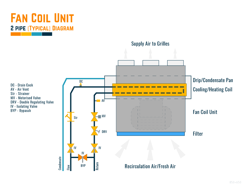
This is a diagram of the obsolete one-pipe pumped system. A 2-pipe HVAC system is one that uses the same piping alternately for hot water heating and chilled water cooling as opposed to a 4-pipe system that uses separate lines for hot and chilled water. 4 Pipe Fan Coil Overview Page 1 of 2 Created on February 2 2018 2 Revision.
In addition a four-pipe system requires more space to accommodate two hydronic piping circuits that run through the building. Two-pipe systems are less flexible than a four-pipe system. Meaning if alterations to the system design or units are made after parts are ordered costs could potentially increase.
In this post youll learn the common electrical components used in HVAC control panels. HVAC systems are of great importance to architectural design efforts for four main reasons. One pipe systems were originally fitted.
LANL Standard Drawings and Details either 1 depict required formatcontent or 2 are templates that are completed by a Design Agency LANL or external AE for a design drawing package in a manner similar to specifications. A 2-pipe HVAC system is one that uses the same piping alternately for hot water heating and chilled water cooling as opposed to a 4-pipe system that uses separate lines for hot and chilled water. Pipe fittings refrigeration valvesfittings valves hvac piping temperature controlmonitoring fire protection system medical steam piping duct symbols plumbing mechanical plumbing symbols and abbreviations abbreviations drawing notations sections and details.
Three-pipe systems are less forgiving to change than two-pipe systems. HVAC and Refrigeration System.
In this post youll learn the common electrical components used in HVAC control panels.
A 4 Pipe Fan coil system is a dual closed loop supply and return water distribution system that serves each suite. However the piping pitch is much more crucial to this system. Four-pipe fan coil unit systems offer several advantages. The entire building is in either heating mode or cooling mode. LANL Standard Drawings and Details either 1 depict required formatcontent or 2 are templates that are completed by a Design Agency LANL or external AE for a design drawing package in a manner similar to specifications. One pipe systems were originally fitted. University of Colorado Boulder CO USA Overview System Description Secondary HVAC Systems Air distribution Room diffusers and air terminals Duct Design Fan characteristics Air Handling Units Water distribution Cooling coils Pipes and pumps Primary HVAC Systems Electric chillers. The 4 pipe system has two available sources heating and cooling which makes the fan coil independent of the system mode. In addition a four-pipe system requires more space to accommodate two hydronic piping circuits that run through the building.
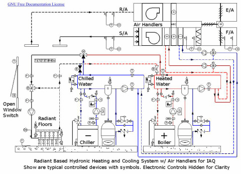
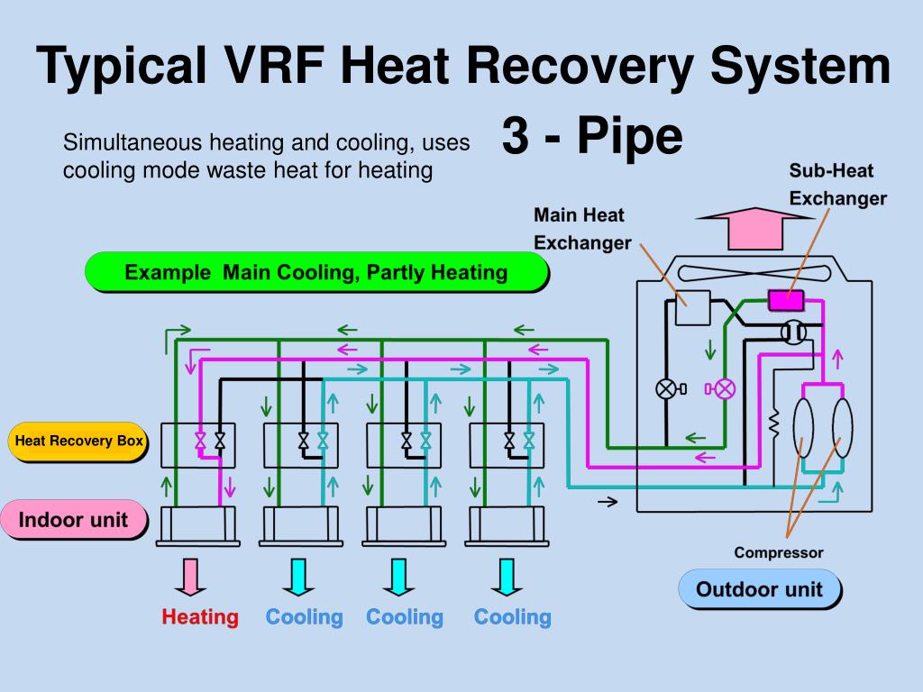
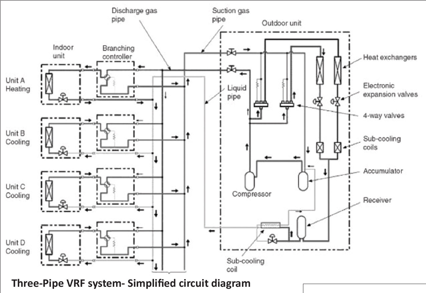
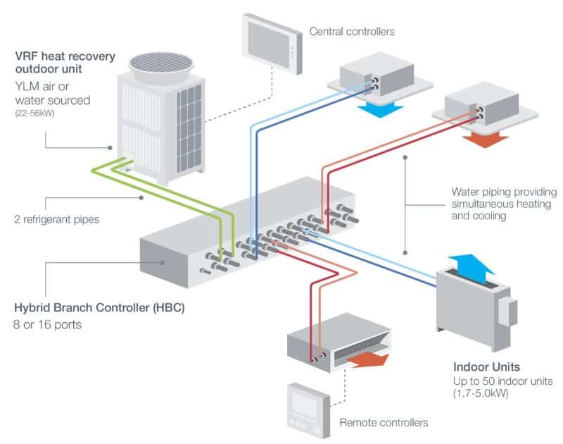
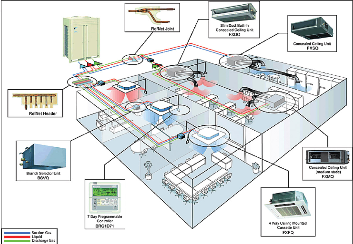
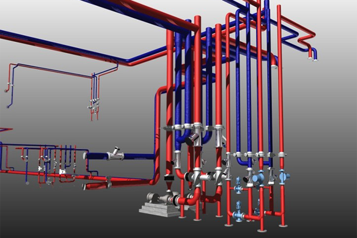
However the piping pitch is much more crucial to this system. The four-pipe fan coil unit system is cost-effective from a chilled water and heating water pumping perspective. Also a Hartford Loop is. VRF systems are engineered systems and use complex refrigerant and oil control circuitry. The required system pipe diameter for example may change if the indoor unit capacity indoor unit type or pipe length fluctuates. Section schematic. DESIGN REQUIREMENTS 21 The design documents shall include a flow diagram of the hydronic system indicating all major components of the system isolation and control valves unionsflanges pipe sizes pressure andor temperature relief devices direction of flow etc.


















Post a Comment for "4 Pipe Hvac System Diagram"